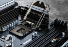
If you have ever picked up a motherboard in your hand, you must have stumbled upon various headers with different pin layouts.
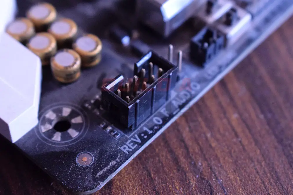
If you look at the bottom of the motherboard, you may find a header named AAFP.
AAFP stands for Analog Audio Front Panel and serves the purpose to connect an audio device like a headphone or a microphone to the front panel of the PC case.
AAFP pin Layout
An AAFP motherboard header features a 10-pin layout with one pin missing at the 8th point. Each pin of the header serves the purpose of establishing the connection between the header and the audio device plugged in.
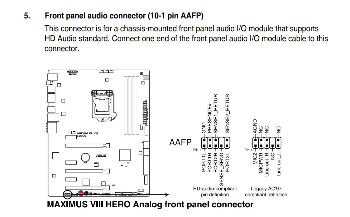
The pins are labeled as follows-
- PORT1L
- GND
- PORT1R
- PRESENCE#
- PORT2R
- SENSE1_RETUR
- SENSE_SEND
- N/A
- PORT2L
- SENSE2_RETUR
AAFP Header Uses
The AAFP header supports an HD Audio standard and can only support a high-definition front-panel audio module. The header can sometimes be also labeled as HD Audio on some motherboards but they are essentially the same.
Older motherboards had the AC97 header which has the same pin layout but didn’t support HD audio devices. Some motherboards support both HD and AC97 audio devices but the user will be required to change the Front Panel Type setting from the BIOS to either HD or AC97 for HD and Legacy AC97 audio devices respectively.
Related: