If you are going to build a computer yourself the first time, then the only problem you are going to face is connecting the cables to the motherboard. There seem to be a dozen cables some of which look identical to each other and you can’t decide which cable goes where?
Don’t worry, this article is a step by step guide to connecting each and every type of cable you find today in modern computers. Before jumping directly on to connecting the cables, you must know the types of cables and connectors you may find on your PC.
Not every following type of connectors and cables may be present in your PC, but just save this guide so that in future you encounter a new type of connector, you can easily do the connection with the help of this guide.
And as always, we are here to help you in the comments section!
Connectors and Connections
1. 24-pin ATX
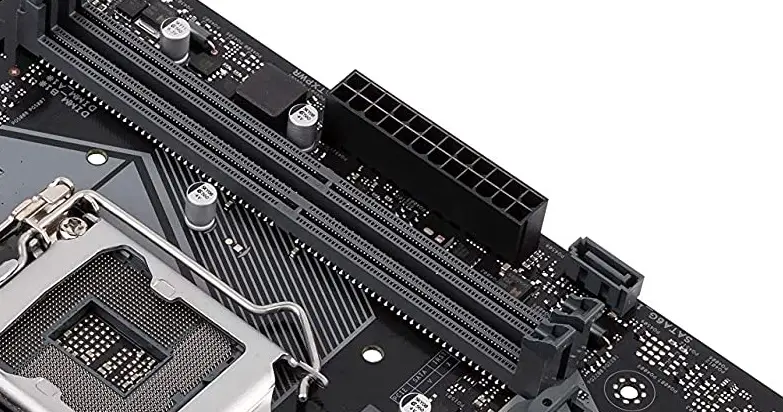
While the older motherboards used to come with a 20 pin power connector, the 24 pin ATX power connector has those additional 4 pins for higher current capability. You can nevertheless use a power supply with a 20 pin connector cable and use it on a 24 pin motherboard.
This connector is responsible for supplying the power throughout the motherboard to different sections including the RAM, PCI, Chipset, Audio section, I/O ports etc.
How to Connect:- The connector from the power supply has a small latch at the middle which makes it easy to know in which direction the connector goes. Some power supplies have 4 additional pins detached from the 20 pin connector. So, all you have to do is combine them both and plug or you can also do it separately if not comfortable with the combination.
To remove that, you will have to open the latch by pressing from the top. It will be stiffer than any of the connectors, so it might take a good amount of force to remove.
Related:- Easily check what motherboard you have
2. EPS
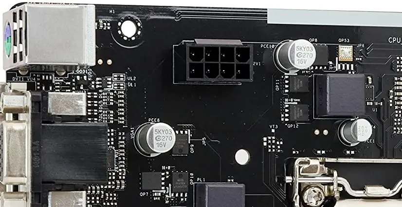
Unlike the 24 pin connector, the EPS connector pin varies in pin count. It can go from a single 4 pins up to a dual 8 pins and that depends upon the tier of the motherboard. This connector is responsible for supplying the power to your VRM section that supplies the regulated voltage to your main processor.
How to Connect:- The EPS connector has a small latch and goes in one way similar to the ATX connector. If you have 2x 4 pin EPS connector ports on the motherboard, then you will have to combine 2x 4 pin EPS connectors from your PSU. Both the latches on them should be aligned.
3. PCI-E
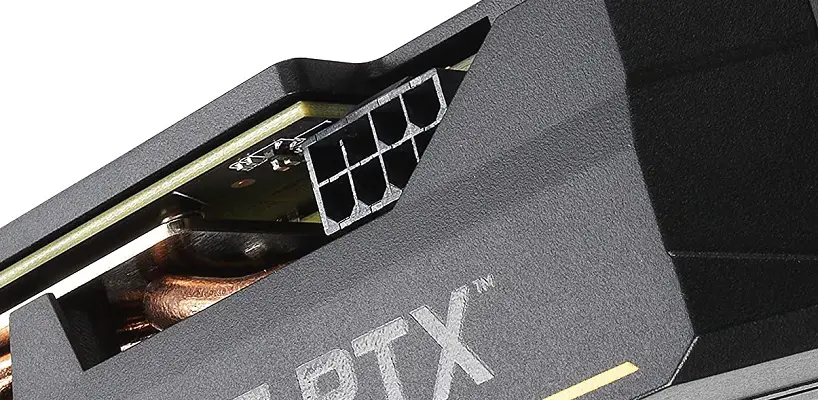
This connector is responsible for supplying the power to your video/graphics card. Generally, it is a 6 pin connector that can go as high as a dual 8 pin connector for a single graphics card.
How to Connect:- The PCI-E connector has a similar method of connecting as the EPS connector has. If your graphics card has an 8 pin connector, then you will have to combine the 2 extra pin connectors to your 6 pins PCI-E connector from your PSU. The same method will be repeated for a graphics card on which 2x 8 pin connectors are present.
4. SATA Power
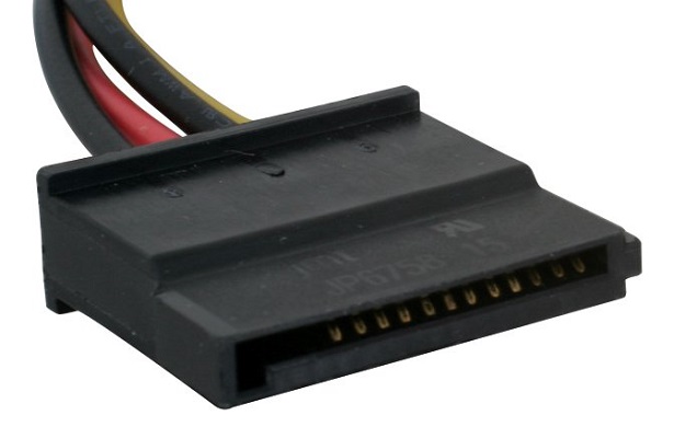
SATA is a 15 pin power connector that can power up a variety of different devices. Generally, it is used for powering up SATA hard drives and Solid State Drives.
How to Connect:- SATA cable has a fixed pattern of pins and can go in one way only which is very easy to know. The connector’s internal design will be in L shape making it easy to know just by looking at it. The connector doesn’t have a latch.
SATA connectors are usually used to power up SATA hard drives and SSDs but there are certain devices like RGB peripherals/adapters/hubs that also use SATA connectors.
Related- What are Motherboard Standoffs?
5. SATA
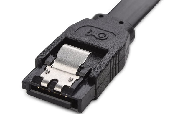
This SATA connector is different from the SATA Power connector because it is used for connecting a SATA storage device directly to the motherboard. It is not responsible for supplying the power to any component.
How to Connect:- SATA cable too has an L shape design inside the connector which makes it easy to know the connection direction. The connector, however, is much smaller than any other connectors mentioned above. Some SATA cables have a latch and some don’t.
6. Molex
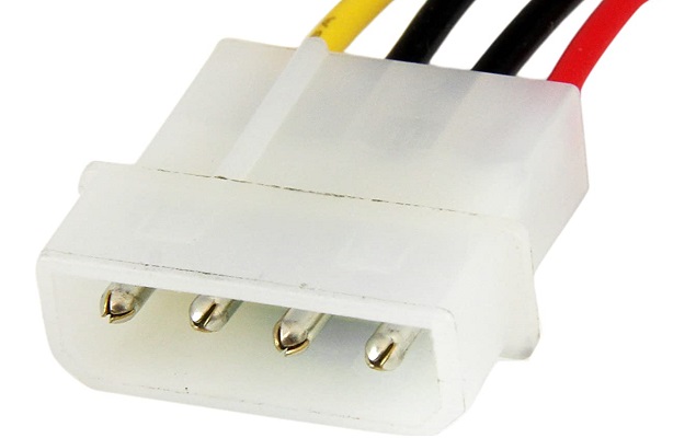
Most of the additional accessories like a chassis fan or an older DVD drive are powered by a Molex connector which is a 4 pin connector that is thicker than the SATA connector. Nowadays, a Molex connector is rarely used in modern computers due to getting replaced by the SATA power connector.
How to Connect:- Molex connector can be connected in both directions. The connector generally requires a lot of force to get perfectly plugged. Some devices use only two pins to receive power and you can connect them into a 4 pin Molex connector leaving 2 female connectors as it is.
7. Fan connector
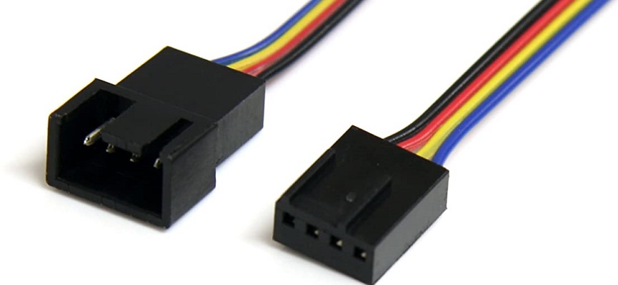
The fan power connector can be a 3 pin or a 4 pin connector both of which have a different use. The 3 pin fan power connector is used for DC fans while the 4 pin connector is used for PWM fans that are easier to control. Note that the CPU_fan header is exactly identical to any other fan header but it will be always mentioned there so that you know where your CPU fan cooler’s fan will be connected. If you connect the CPU fan to some other header, it may not work.
How to Connect:- First check how many pinholes do your fan cable has. If it has 3, then it can go in a 3 pin as well as 4 pin header. Connecting on a 4 pin header will leave out the 4th pin on the header as not connected and doesn’t make your fan incompatible. You will only lose the PWM feature as your fan has a 3 pin connector.
8. RGB and ARGB headers
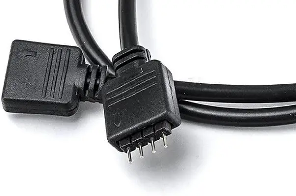
RGB and ARGB headers are used to connect RGB peripherals to the motherboard. RGB header is a 4 pin power connector with a 12V rating while the ARGB header is a 3 pin power connector with a 5V rating. ARGB header has the capability to control individual LEDs while the RGB header has limited control.
How to Connect:- RGB header has 4 pins while the ARGB header has only 3. While an RGB device that has a 4 pin connector can be connected to an ARGB header with 3 pins, an ARGB device with a 3 pin connector can’t be connected to a 4 pin RGB header.
RGB connector can go in both directions while ARGB connector can go in one direction only.
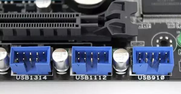
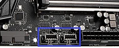
9. USB 3.0 header
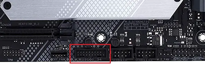
The USB 3.0 header is for supplying the power to the front panel USB 3.0 port on a chassis.
How to Connect:- USB 3.0 header has 20 pins in total. The USB 3.0 connector has a small extra plastic on one side which fills the cutout on the header on the motherboard. This makes it go in one direction only.
10. USB 2.0 header
A motherboard also has a USB 2.0 header for supplying the power to the front panel USB 2.0 ports.
How to Connect:- A USB 2.0 header on a motherboard has a 10 pin layout with one pin at the last spot missing. This will make your connector go in only one direction. The connector cable will be present in your chassis connected to the front panel ports.
11. USB Type C header
Some chassis today come with a front panel USB Type C port and can only be used if the motherboard in use has a Type C header.
How to Connect:- Type C header is smaller than the Type A header and so does the connector. Some motherboards and cases come with a USB Type C header and Type C ports respectively. If both of your motherboard and case have it, then you can connect the Type C cable from your case to your motherboard Type C header.
12. Audio header
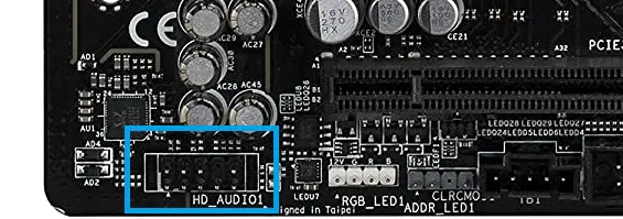
It is a connector that is used to supply power to the Audio and Mic jacks at the front panel for easy access to audio through a speaker or a headphone.
How to Connect:- The front Audio Header has a 10 pin layout but one pin is missing at the 8th spot and thus the connector will go in one way only. Usually, this header is present at the bottom of the motherboard and most of the boards will have their name mentioned below the header.
13. Front panel header
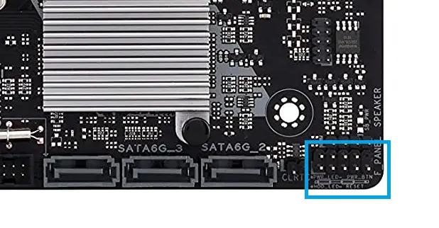
The front panel header consists of a variety of connectors used for different functions like Power, Reset, Hard drive LED and Power LED. It is generally present at the bottom right corner of a motherboard.
How to Connect:- Front panel header has 4 different headers but they are close to one another in a way that they seem to be a single header. There are a total of 9 pins, the 9th one being a not-connection pin. It makes it easy to know the connection direction.
The Power Connector will be connected to the top 2 pin header where there are 4 pins in total while the Reset Connector will be just below it where the total pins are 5(which includes the 9th pin). Adjacent to the Power Connector header will be two pins each of which will be used for individual Power LED connectors. Those two LED connectors will be named PWR_LED+ and PWR_LED-.
Similarly, the adjacent two-pin header to the Reset Connector will be used for the HDD LED connector. Consider the following diagram for an easy understanding.